
For a while now I’ve been building a CAN-controlled Power Distribution Module (PDM) for my track car — the kind of device that replaces a fuse box and a pile of relays with a single microcontroller that switches loads based on programmable logic. Fans, fuel pumps, lighting, ignition, whatever needs power and needs it conditionally.
The hardware side of that project has grown into something bigger than a one-off PCB, so I’m open sourcing it as PDMKit — a two-part platform consisting of a configuration app and the firmware it talks to.
- PDMKit App — a cross-platform desktop app for visually configuring pin logic
- PDMKit Firmware — the ESP-IDF firmware that runs on the ESP32-P4 and actually executes those rules
Both are released under the PolyForm Noncommercial License — free to use, study, and modify for non-commercial purposes.
Why build this
Most PDMs on the market are either closed-source, expensive, or locked into a vendor’s own configuration tool with limited logic capability. I wanted something where the rule engine wasn’t a black box — where I could define arbitrary combinational and stateful logic across GPIO and CAN inputs, see it visually, and deploy it to hardware without hand-rolling firmware changes every time I wanted to add a condition.
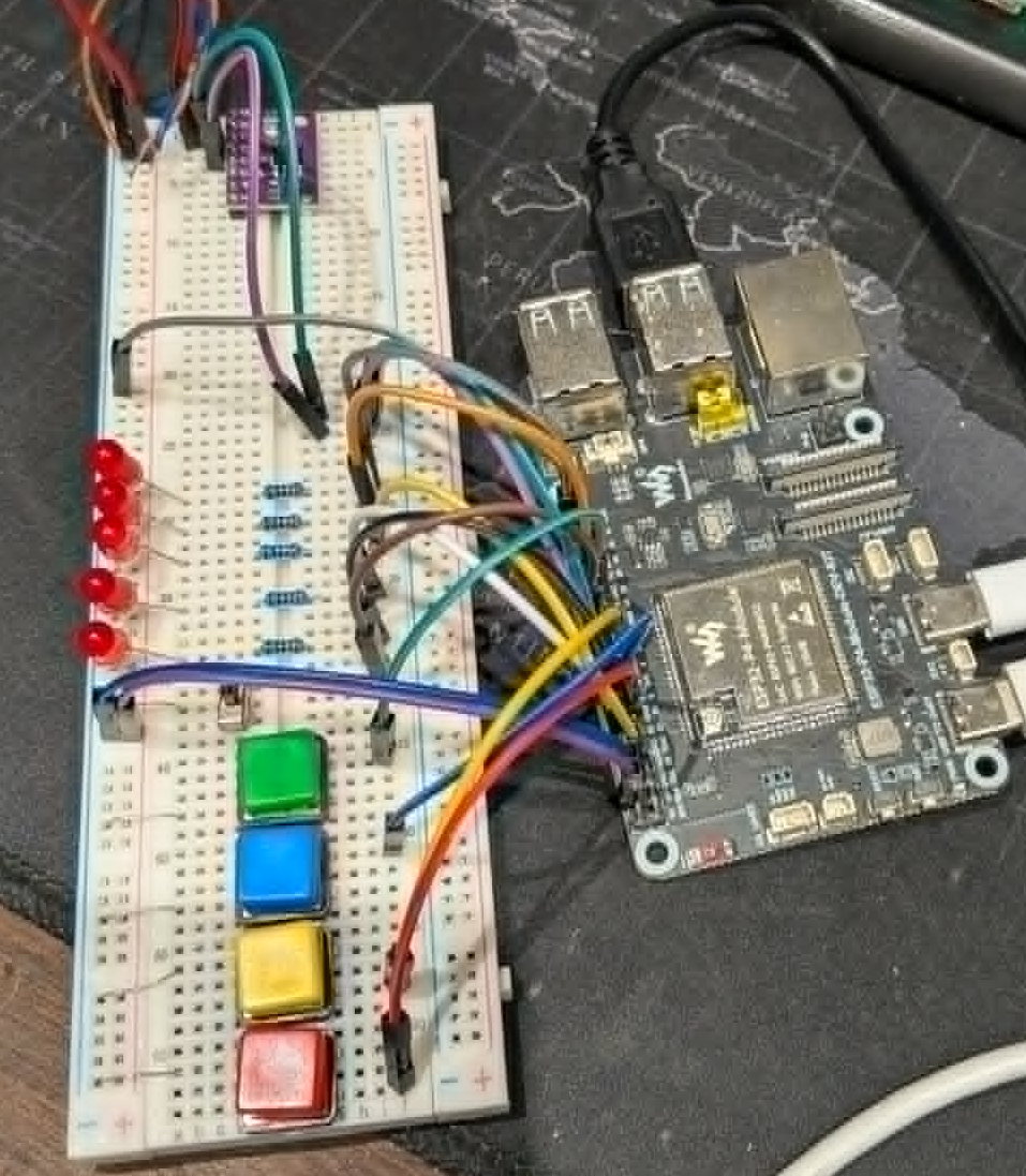
The ESP32-P4 was a natural fit: plenty of GPIO, USB JTAG debugging built in, and enough headroom to run a proper rule evaluation loop alongside CAN I/O.
Here’s the dev kit and breadboard prototype mid-build, running through GPIO logic with buttons and LEDs before anything touches the actual car:
What PDMKit actually does
PDMKit splits cleanly into two halves.
The App is a Tauri desktop application (React + TypeScript frontend, Rust shell) that gives you a visual interface for:
- Configuring GPIO pins as inputs or outputs, with labeling
- Grouping related pins together for organization
- Building logical expressions with AND, OR, XOR, and NOT
- Defining timed events, thresholds, and conditional rules
- Monitoring real-time device state over the wire
- Managing oscillator and PWM output settings
- Deploying the resulting configuration straight to the device over USB JTAG
The Firmware runs on the ESP32-P4 itself, built on ESP-IDF v5.5. It’s the thing that actually receives a configuration from the app and executes it — evaluating the logic rules against live pin and CAN state, in real time, on the device.
Pin management
Configuring and labeling GPIO pins, with everything organized so it doesn’t turn into a wall of unlabeled numbers:

Groups
Related pins get grouped together, which matters a lot once you’re past a handful of I/O — think “cooling fans,” “ignition circuit,” “aux lighting” as first-class groupings rather than a flat pin list:

Variables
Reusable variables and expressions so you’re not duplicating the same threshold or condition across multiple rules:

The logic canvas
This is the centerpiece — a visual, node-based canvas for building the actual logic that drives outputs. Combinational logic, timing behavior, stateful conditions, protective cutoffs, all wired together visually instead of buried in a switch statement:

Rules configuration
And the rules panel, where timing, thresholds, and more complex expressions get assembled into something the firmware can execute:

Under the hood
App stack:
- React 18 + TypeScript + Vite
- Tauri (Rust + native webview) for the desktop shell
- Zustand for state management
- Tailwind CSS for styling
Firmware stack:
- ESP-IDF v5.5, targeting the ESP32-P4
- USB JTAG debugging built in — no external programmer needed
- NVS-backed key-value storage helper for persisting config on-device
- Full VS Code integration: build/flash/monitor tasks, OpenOCD + GDB launch config, and clangd for IntelliSense using the ESP-IDF toolchain
The firmware repo structure is intentionally minimal right now — an app_main entry point and a small helper module for NVS storage — because most of the complexity lives in how the app compiles logic definitions down into something the firmware can evaluate efficiently. That protocol and rule-execution layer is where most of the ongoing work is happening.
Getting started
If you want to poke at it yourself:
# Appgit clone https://github.com/johngreen-dev/PDMKit_App.gitcd PDMKit_Appnpm installnpm run tauri dev
# Firmware (requires ESP-IDF v5.5 on PATH)git clone https://github.com/johngreen-dev/PDMKit_Firmware.gitcd PDMKit_Firmwareidf.py buildidf.py -p COM6 flash monitor
You’ll need an ESP32-P4 dev board to actually flash and test against — I’ve been using the Waveshare ESP32-P4-Module-DEV-KIT, which has been solid for this.
What’s next
The near-term roadmap is mostly about closing the loop between “logic defined in the app” and “logic running reliably on hardware”: finishing out the CAN-based rule types, hardening the deploy protocol between app and device, and eventually moving this off a breadboard and onto the custom PCB I’ve been designing for the actual PDM (TJA1051 CAN transceiver, automotive-rated power input, the works).
Both repos are open for issues and pull requests if you want to follow along or contribute — see CONTRIBUTING.md in the firmware repo for guidelines that apply across both projects.
Categories: Projects

Leave a comment